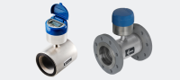


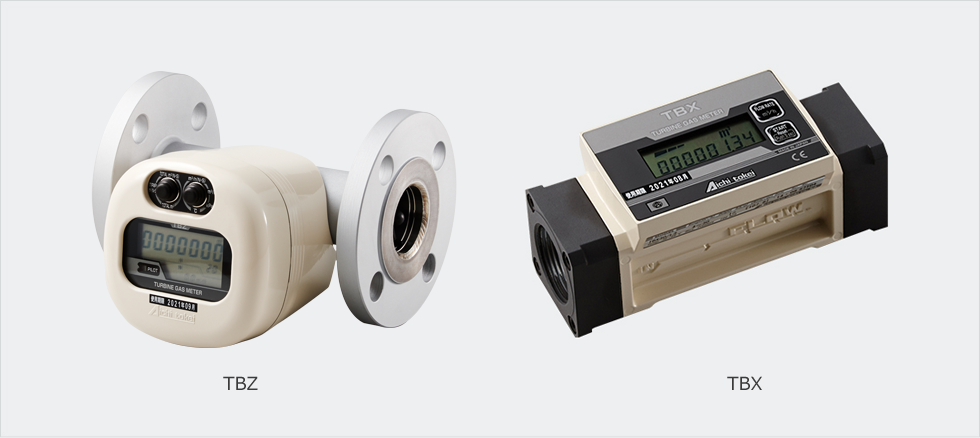
TBX/TBZ Turbine Gas Meters for Flow Management
Xuất sứ: Japan
Nhà cung cấp: Pites
Hãng sản xuất: Aichi Tokei Denki
TBZ60, TBZ150, TBZ300, TBX30, TBX100, TBX100F, TBX150F, YKDS32, YKDS40, YKDS50, YF50, YDF40, YDF50, YDF80 | TBX/TBZ Đồng hồ đo tua bin khí cho quản lý dòng chảy Aichi Tokei Nhật Bản chính hãng mới 100% có COCQ
Click vào đây nếu bạn có thiết bị muốn sửa chữa!!!
Tính năng, đặc điểm
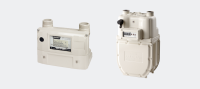
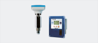
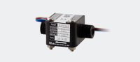
- Máy đo tua bin trong Series TBZ và TBX được phát triển để kiểm soát mức tiêu thụ khí của từng thiết bị như nồi hơi nhỏ gọn và các lò công nghiệp khác nhau.
- Các sản phẩm hiện thực hóa một thiết kế thông minh với thân máy gọn nhẹ và hỗ trợ nhiều phép đo bao gồm áp suất làm việc tối đa và tốc độ dòng đo tối đa.
- Hơn nữa, 2 hệ thống tích hợp các máy phát xung cho phép bạn thiết lập hệ thống đọc đồng hồ từ xa và hệ thống điều khiển năng lượng.
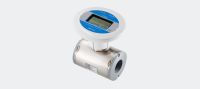
- Series TBZ thậm chí còn điều chỉnh nhiệt độ và áp suất để cho phép bạn đọc mức tiêu thụ khí trong điều kiện chuyển đổi tiêu chuẩn.
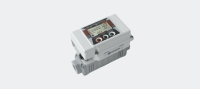
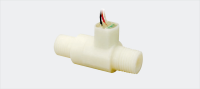
- Mô hình cung cấp điện bên ngoài TBX-D đã được thêm mới vào dòng sản phẩm của dòng TBX.
- Bạn có thể chọn mô hình phù hợp nhất với các ứng dụng của mình để có khả năng sử dụng tốt hơn.
*Lưu ý) TBX30, TBX100 và TBX100F tuân thủ CE.
(Sản phẩm hợp tác phát triển với Tokyo Gas Co., Ltd.)
- Áp suất làm việc tối đa bao gồm áp suất thấp, trung bình và cao.
- Vị trí lắp đặt: hầu hết mọi vị trí

- Được trang bị hai hệ thống máy phát xung.
- Hỗ trợ nhiều loại khí và phạm vi ứng dụng rộng hơn.
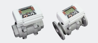
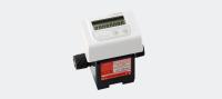
- Màn hình LCD cung cấp cho bạn nhiều thông tin hơn.
- Điều chỉnh nhiệt độ và áp suất. (Dòng TBZ).
- Hoạt động không ngừng trong bảy năm. (Đối với thông số kỹ thuật của pin)
Ứng dụng ví dụ
- Quản lý và kiểm soát các luồng khí của thiết bị đốt như đầu đốt, nồi hơi và lò nung.
- Quản lý và kiểm soát dòng chảy của máy tạo nước nóng và lạnh ở kích thước nhỏ gọn đến trung bình.
- Quản lý và kiểm soát dòng chảy của tủ lạnh gas.
- Quản lý và kiểm soát dòng khí như một phần của thiết bị đo đạc thực vật.
- Đối với các thiết bị thí nghiệm khác nhau liên quan đến dòng khí.
System drawing

Specifications
The model with the correcting function (TBZ series)
|
Basic model |
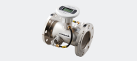
TBZ60 |
TBZ150 |
TBZ300 |
|||||||
|---|---|---|---|---|---|---|---|---|---|---|
|
Model name |
Flow rate correcting model (with the functions of temperature and pressure correction) |
- |
TBZ |
TBZ |
- |
TBZ |
TBZ |
- |
TBZ |
TBZ |
|
Actual flow rate model (without the functions of temperature and pressure) |
TBZ |
- |
- |
TBZ |
- |
- |
TBZ |
- |
- |
|
|
Operating flow rate range *1 |
6~60m3/h |
12.5~150m3/h |
30~300m3/h |
|||||||
|
Maximum operating pressure |
980kPa |
350kPa |
980kPa |
980kPa |
350kPa |
980kPa |
980kPa |
350kPa |
980kPa |
|
|
Accuracy |
Flow rate measuring parts |
±1%FS and ±3%RS |
||||||||
|
Operator parts and temperature and pressure correction parts |
- |
±2% |
±3% |
- |
±2% |
±3% |
- |
±2% |
±3% |
|
|
Display |
Corrected gross accumulated flow rate |
Large LCD in 9 digits with minimum reading of 10 L |
Large LCD in 9 digits with minimum reading of 100 L |
|||||||
|
Trip flow rate *2 |
Large LCD in 8 digits with minimum reading of 10 L |
Large LCD in 8 digits with minimum reading of 100 L |
||||||||
|
Unadjusted gross accumulated flow rate *3 |
Large LCD in 9 digits with minimum reading of 10 L |
Large LCD in 9 digits with minimum reading of 100 L |
||||||||
|
Corrected instantaneous flow rate |
LCD in 4 digits with minimum reading of 0.1 m3/h |
LCD in 4 digits with minimum reading of 1 m3/h |
||||||||
|
Unadjusted instantaneous flow rate |
LCD in 4 digits with minimum reading of 0.1 m3/h |
LCD in 4 digits with minimum reading of 1 m3/h |
||||||||
|
Temperature |
LCD in 3 digits with minimum reading of 0.1 m3/h |
|||||||||
|
Pressure |
LCD in 3 digits with minimum reading of 0.1 m3/h |
|||||||||
|
Diameters of connected parts |
JIS 10K 40A flange |
JIS 10K 50A flange |
JIS 10K 80A flange |
|||||||
|
Operating temperature range |
-10℃~+60℃ |
|||||||||
|
Measurable gases *4 |
Town gas, LPG, nitrogen, etc. |
|||||||||
|
Mounting position |
Horizontal and Vertical (Display supports both directions.) |
|||||||||
|
Installation location |
Indoor and outdoor * 5 |
|||||||||
|
Case structure |
Drip-proof structure, IPX 2 equivalent (JIS-CO920) |
|||||||||
|
Power source |
Built-in lithium battery |
|||||||||
|
Output signal |
Two systems of open collectors (corrected pulse and unadjusted pulse * 6) |
|||||||||
|
Standard pulse unit width * 7 |
100 L/P |
|||||||||
|
Materials |
Main piping: Stainless steel; Flange: Steel; Display: Aluminum alloy |
|||||||||
|
Temperature sensor |
Platinum resistance temperature detector thermal sensor: JIS A class |
|||||||||
|
Pressure sensor |
Semiconductor type pressure sensor (High precision) |
|||||||||
|
Mass |
5.3kg |
6.0kg |
9.4kg |
|||||||
*1. Operating flow rate range is the range of the actual flow (unadjusted flow rate)..
*2. Corrected trip accumulated flow rate for the flow rate correction model (with temperature and pressure correction) and unadjusted trip accumulated flow rate for the actual flow rate model (without temperature and pressure correction)..
*3. Under the conditions of pressure 100 kPa or higher for the -3.5 model and 350 kPa or higher for the – 9.9 model where the temperature is at 25°C..
*4. Prevent oil mist (Carbide grade C5 or higher), dust particles and the like from entering into the meter..
*5. Avoid direct contact of water onto the meter if the meter is installed outdoors..
*6: Unadjusted pulse and high-density pulse are the actual pulse synchronized with the rotation of impellers..
*7. TBZ uses corrected pulse while TBX uses unit pulse.
Specifications of actual flow display model (TBX series)
|
Model type |
TBX30 |
TBX100 |
TBX100F |
TBX150F |
|
|---|---|---|---|---|---|
|
Operating flow rate range *1 |
4~30m3/h |
10~100m3/h |
10~100m3/h |
12.5~150m3/h |
|
|
Maximum operating pressure |
100kPa |
||||
|
Accuracy |
Flow rate measuring parts |
±1%FS |
|||
|
Display |
Trip flow rate *2 |
Large LCD in 6 digits with minimum reading of 10 L |
LCD in 6 digits with minimum reading of 100 L |
||
|
Unadjusted gross accumulated flow rate *3 |
Large LCD in 8 digits with minimum reading of 10 L |
LCD in 8 digits with minimum reading of 100 L |
|||
|
Unadjusted instantaneous flow rate |
LCD in 3 digits with minimum reading of 0.1m3/h |
LCD in 4 digits with minimum reading of 0.1m3/h |
LCD in 3 digits with minimum reading of 1m3/h |
||
|
Diameters of connected parts |
Rc1 1/2、Rc1 1/4 |
Rc2 |
JIS 10K 50A flange |
||
|
Operating temperature range |
-10℃~+60℃ |
||||
|
Measurable gases *4 |
Town gas, LPG, nitrogen, etc. |
||||
|
Mounting position |
Horizontal and vertical |
||||
|
Installation location |
Indoor |
||||
|
Power source |
Built-in lithium battery or external power supply (24 VDC) |
||||
|
Output signal |
Two systems of open-drain output (unit pulse and high-density pulse * 5) |
||||
|
Standard pulse unit width * 6 |
TBX30 and TBX100: 10 L/P; TBX150: 100 L/P |
||||
|
Materials |
Aluminum alloy |
Cast iron |
Aluminum alloy |
||
|
Mass |
0.8kg |
1.8kg |
7.0kg |
2.5kg |
|
*1. Operating flow rate range is the range of the actual flow (unadjusted flow rate)..
*2. Corrected trip accumulated flow rate for the flow rate correction model (with temperature and pressure correction) and unadjusted trip accumulated flow rate.
for the actual flow rate model (without temperature and pressure correction)..
*3. In the conditions of pressure 100 kPa or higher for the -3.5 model and 350 kPa or higher for the – 9.9 model where the temperature is at 25°C.
*4. Prevent oil mist (Carbide grade C5 or higher), dust particles and the like from entering into the meter..
*5: Unadjusted pulse and high-density pulse are the actual pulse synchronized with the rotation of impellers..
*6. TBZ uses a corrected pulse while TBX uses a unit pulse.
Dimensions
Dimensions of the turbine meter TBZ

(Unit: mm)
|
Model |
L |
H |
W |
JIS 10K flange |
|||
|---|---|---|---|---|---|---|---|
|
φD |
φd |
aφb |
Diameters |
||||
|
TBZ60 |
200 |
150 |
197 |
140 |
105 |
4-19 |
40A |
|
TBZ150 |
220 |
158 |
211 |
155 |
120 |
4-19 |
50A |
|
TBZ300 |
250 |
185 |
246 |
185 |
150 |
8-19 |
80A |
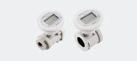
Dimensions of the turbine meter TBX

For TBX100F, the indicator can be moved freely, wherein the meter can accommodate the direction of the gas flow. The indicator can also be removed to be used as a remote display.
(Unit: mm)
|
Model |
L |
H |
W |
|---|---|---|---|
|
TBX30 |
170 |
74 |
73 |
|
TBX100 |
200 |
100 |
85 |
|
TBX100F |
200 |
161 |
φ155 |
|
TBX150F |
200 |
148 |
φ155 |
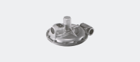
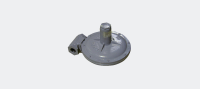
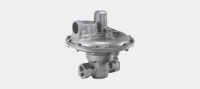
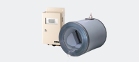
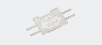
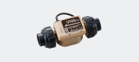
Strainer (sold separately)
Make sure to install the strainer in the upstream side of the flow meter in order to maintain the performance of the flow meter as long as possible.
* Consideration of pressure loss will be necessary.
Standard specifications
|
Model |
YKDS32 |
YKDS40 |
YKDS50 |
YF50 |
YDF40 |
YDF50 |
YDF80 |
|---|---|---|---|---|---|---|---|
|
Maximum operating pressure (kPa) |
500 |
500 |
500 |
500 |
980 |
980 |
980 |
|
Body material |
FCD450 |
FCD450 |
FCD450 |
FCD200 |
FCD-S |
FCD-S |
FCD-S |
|
Diameter (A) |
32 |
40 |
50 |
50 |
40 |
50 |
80 |
|
Connection |
Rc1・1/4 |
Rc1・1/2 |
Rc2 |
JIS10K(FF) |
JIS10K(RF) |
||
|
Mass (kg) |
2.3 |
2.9 |
4.5 |
8.2 |
8.5 |
11 |
15 |
|
Supported models |
TBX30(32A) |
TBX30(40A) |
TBX100 |
TBX100F・150F |
TBZ60 |
TBZ150 |
TBZ300 |
Dimensions: Screw type
(Unit: mm)
|
Model |
A |
L |
H (in approximate) |
|---|---|---|---|
|
YKDS32 |
32 |
145 |
105 |
|
YKDS40 |
40 |
160 |
110 |
|
YKDS50 |
50 |
180 |
130 |

Dimensions: Flange type
(Unit: mm)
|
Model |
A |
L |
H (in approximate) |
|---|---|---|---|
|
YF50 |
50 |
220 |
130 |
|
YDF40 |
40 |
240 |
155 |
|
YDF50 |
50 |
250 |
170 |
|
YDF80 |
80 |
320 |
215 |